Control algorithms play a central role in power electronics, governing how converters regulate voltage and current, manage power flow and respond to changing electrical conditions. This article examines their role in grid-tied solar inverters, including MPPT, grid synchronisation, current control and protection.
Electrical conditions around a power converter change constantly. A solar inverter has to draw the available power from its PV modules while staying synchronised with the grid. An EV charger has to deliver power at the rate the vehicle’s battery can accept. In both cases, a control algorithm decides how the converter responds to what it measures.
Control algorithms turn electrical measurements into switching commands for the converter’s semiconductor devices. They regulate voltage and current, manage power flow and set how the converter reacts to disturbances. The quality of that design shows up in efficiency, power quality and reliability, and in how quickly the converter recovers when conditions change.
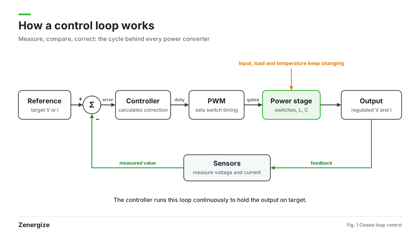
A power converter is built from semiconductor switches, passive components such as inductors and capacitors, sensing circuits and a controller. The controller measures voltage and current, compares the readings with reference values and calculates the switching action needed to close the gap. It repeats this cycle continuously to hold the output where it should be.
Most converters drive their switches with pulse width modulation (PWM). By changing the duty cycle, which is the share of each switching period a device stays on, the controller sets how much energy passes through the converter. Feedback loops then correct any difference between the measured and reference values.
How precisely a converter regulates its output depends on two things: the accuracy of these calculations and how fast the controller can run them.
A grid-tied solar inverter runs several control functions at once inside a single conversion system. It works in two stages. The first extracts power from the PV array, and the second converts that power into AC the grid can accept.
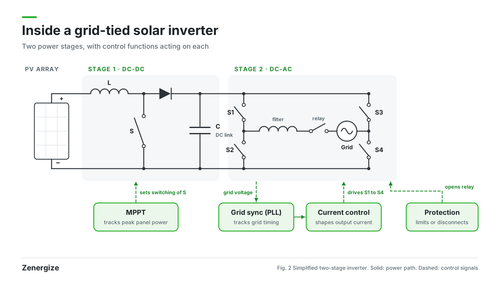
MPPT controls the DC side. A PV module delivers its maximum power at one particular combination of voltage and current, and that point moves with irradiance and temperature. The MPPT algorithm keeps checking the module’s operating point and adjusts the voltage reference to stay at the peak.
Common methods include Perturb and Observe (P&O) and Incremental Conductance. They track the peak in different ways, and they are judged on two counts: how accurately they hold it, and how quickly they follow changes in sunlight.
On the AC side, these loops govern how power enters the utility network. A phase-locked loop (PLL) estimates the phase angle and frequency of the grid voltage and gives the inverter its timing reference. Current control loops then shape the output current to match the active and reactive power references. Their design sets the inverter’s power factor, the quality of its current waveform and how it reacts when grid voltage or frequency shifts.
Protection algorithms check voltage, current and frequency against set operating limits. When a value moves outside its permitted range, the controller limits output or disconnects the inverter from the grid. The grid standards the inverter is certified to define how it responds and how fast.
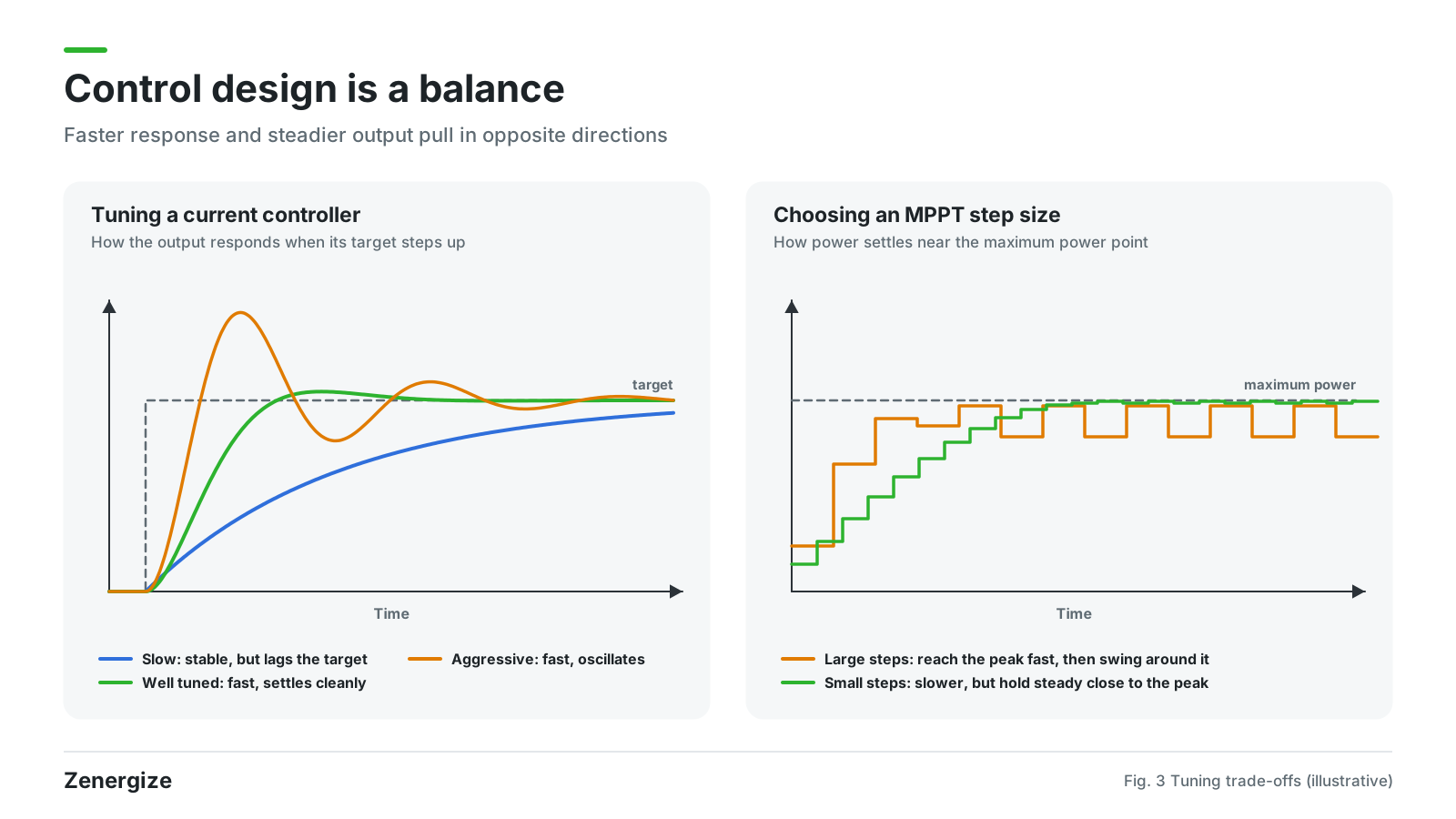
Each of these functions involves trade-offs between stability, response time and measurement accuracy. A current controller tuned for fast response reacts quickly to a disturbance, but with too little stability margin it starts to oscillate. MPPT faces a similar choice: faster tracking means larger fluctuations around the maximum power point once the algorithm reaches it.
The hardware limits what the control can achieve. Switching frequency, sensor resolution, processor speed, circuit parasitics and component tolerances all affect how accurately the controller’s commands are carried out. Engineers have to account for these while designing the power stage and the firmware together, then verify the result through simulation and lab testing.
Grid-tied inverters add one more variable: the grid itself. Voltage and frequency behave differently from one distribution network to the next. An inverter that performs well on a lab supply still has to prove itself against the conditions it will meet in the field and the compliance requirements that apply there.
At Zenergize, we develop the control functions of our grid-tied solar inverters alongside the power electronics they run on. MPPT, grid synchronisation, current regulation and protection are built for the specific power stage, so the inverter can handle solar conversion and grid interaction across its full operating range.
The demands on control keep rising as the hardware improves. Silicon carbide devices switch faster than silicon, which leaves the controller less time to act and less margin for error. The quality of that control decides how efficiently and reliably a converter performs, and that is why control algorithm development sits at the centre of how we design power conversion equipment.
Written by
Armaan Garg
View LinkedInRelated Articles
